Centenary of Powered Flight Project
PROJECT:
Commemoration of 1903 - 2003: Centenary of Powered Flight
By "As Many School Student Groups As Possible"
Project Initiator:
Roger R Marks, Member of AHSA (Aviation Historical Society of Australia)
E-mail: [email protected] Web Site: http://www.qaww2.com/
PROJECT BULLETIN NO 5 (includes all previous)
Date: 10 June 2003
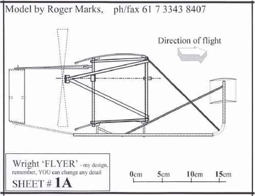
Sketch above (earlier version) started you off and got you thinking. It's now completed and, YES, you're right - I've now included the RUDDER panels.
Here are sufficient PLANS / sketches to allow you to complete your Wright "FLYER". I've now added a Sheet 8 showing my suggestions for the LAUNCHER !
Other Plans etc., are at bottom of this page.
Disclaimer
A friend has warned me to ensure nobody thinks to SUE (me) if model doesn't fly!.
Seriously though, it is to be clearly understood that participation in the making or flying of a representative model of the Wright Flyer, be it like mine or any I point you to is entirely at your own risk. I make no guarantees as to effectiveness of any procedures to which this website may guide you. Any conditions of use of say glues or other materials indicated via this website are to be as the relevant manufactures may promulgate and it is up to you to ensure they (instructions for use etc,.) are obtained and followed. All care has been applied in formulating this commemorative initiative but no claim whatsoever will be entertained by me for any disadvantage or unfavourable outcome. You, the user must carry all responsibility for safe conduct of such participation.
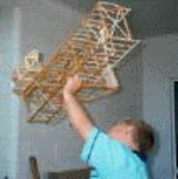
I do wish all participants a safe and enjoyable experience. I'd love to see photos etc., of your results. In fact, here is a good spot to show you my grandson Brandon holding my prototype 'FLYER'.
CONTENTS
- Historical Background
- Commemorative Project Aims
- Suggested Design
- Flyer
- Launcher - now added
- Notes On Materials -
- Small Section Pine Vs Balsa From Hobby Stores
Wood
Traditional aircraft modeling 'wood' is BALSA, a very light weight, easy to cut and work variety. Around $12 AUD will provide ample for this model but in the interest of added strength ordinary PINE or other softwood will better suit some parts of the model. Where you choose to use PINE it will be necessary to have access to a hobby (or industrial) woodworking SAW bench. Talk to Teacher, 'Dad' or another adult about this.
Metal Elements
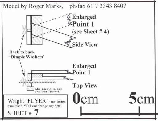
I set out using Aluminum tube available from hobby shops because I wanted to drive the two propellor shafts by RUBBER bands running on wooden pulley / wheels like the Wrights used bicycle chains on sprockets. I used 2.5 mm outer diameter (OD) tube INSIDE short bits of 3 mm inside diameter (ID) tube as bearings, but the friction was still too much. Also, although I fashioned my 'pulleys' (on a wood turning lathe) with ample crowning I found I needed rubber band (drive chains) cut from motor cycle tubes !! So, this time I'm going for individually rubber powered simple prop shafts fashioned from 1 mm diam spring steel wire. That wire is available at hobby shops and while you are there try to pick up appropriate dimpled washers to use, dimple against dimple as THRUST bearings.
Glues
I have considered four (4) types.
PVA, an easy to use very safe type but requiring a degree of 'clamping' which may not be too difficult to apply. However, given your model may 'land in wet grass' from time to time it's good to realise PVA is not weatherproof. It's kind to hands (skin) and not offensive or hurtful to 'the nose'. Plus, most households will have some on hand from craft work activities.
Model Aircraft CEMENT (MAC) is obtainable from hobby stores. It's quick drying and usually benefits from 'pinning' with simple dressmaking glass headed pins. It has an acetone base and characteristic smell. Try not to inhale its fumes as repeated exposure will do you no good.
Premium Bond Craft Glue (PBCG) is available at craft shops. It's a bit like contact cement although you don't need to 'apply to both surfaces'. It seems to be a bit more reliable than the MAC and still easy on your hands. It's not safe to inhale etc., but I found it more time accommodating - i.e. it was not so demanding on the return of the pin stopper.
Epoxy Resin (ER) - two pack such as 5 minute ARALDITE.. This is the most reliable / strong but very time-demanding in that you usually need to make up MORE than you need or can even put in place before it SETS ! Also, it is extremely necessary to keep it off your skin (best wear gloves) and the fumes again are not good to inhale. Given all those disadvantages it is the most weatherproof.
All things considered I now feel the PBCG is the best to use here.
Rubber Bands
Available from office supply stores, I chose a packet of several hundred, 'Size 64', (about 4 mm wide and 60 mm (Diameter ?) ), because I knew there would be BREAKAGES. Also, it's surprising how easily the bands seem to 'age' with time extended on the model. Best to change for a new set 'every now and again'.
Appendices *
(* not included herein)
1) Excerpt from "History of Aviation" by J W R Taylor and Kenneth Munson "Threshold of Success" i.e. pages 44 - 51
2) Article from "Flying Aces" Magazine of April 1937, by Henry Struck, entitled "Build and Fly the Original Wright Biplane". (a small rubber powered design - 8 pages) - downloaded from www.ualberta.ca/~khorne )
3) Drawing by Frank Munger published by Flight International, 2003.
Historical Background
On 17 December 1903, Wilbur and his brother Orville Wright are credited with the first "sustained flight" in a "heavier than its own volume of air machine".
They called their aeroplane the "Flyer" and we now refer to it as the "Wright Flyer". It was strange looking by our present day concept of an aeroplane and its manner of take-off also was strange.
It looked like a large box kite with a smaller box kite perched in front and two tall thin rudder panels behind. The Wright brothers had to design and build a suitably powerful but light weight metal engine which they devised to drive two large pusher propellers.
The single pilot lay prone on top of the lower wing and to the side of the engine to counter-balance its weight. With one hand he moved a lever controlling the "tilt angle" of the small box-kite in front serving to dive or climb the plane and with the other hand he operated the engine's throttle.
To turn their aeroplane the Wright brothers connected ropes tied from outer edges of the wings (and to the rudders) through various pulleys to a sideways sliding cradle located under the pilot's thighs. Anchored by his feet on the fixed footrests, the pilot moved his body (thighs) to one side or the other causing the cradle to move and tug certain ropes. These ropes in turn caused parts of the wings to flex or warp, and so the airflow over the wings was changed, inducing the plane to turn.
This method of control was very sensitive and demanded constant attention from the pilot. The aircraft was by nature of its design very UNSTABLE*. Later development by other designers showed the great value of stabilising features like the tail plane (rudder and elevators) of the conventional aeroplanes of today.
The Wright Flyer had no wheels (undercarriage) as we are accustomed to seeing on aeroplanes. It landed on wooden skids. Moreover, it was commonly catapulted into the air "on take-off", something like how we see planes being shot off the foredeck of modern aircraft carriers. The Wright brothers devised a system referred to as the "tower and falling weight". Essentially, the Flyer was set on a wooden launching rail facing into the wind. A tower was located behind it and a rope led through pulleys from a heavy weight perched high in the tower, to a cradle carrying the aeroplane. When the plane's engine was started, a lever was pulled near the tower allowing the heavy weight to fall to ground while the rope to which it was attached dragged the cradle forward, launching the plane into the air.
The Wright brothers devised their OWN wind tunnel. For the more ambitious and suitably advanced students, perhaps they too could be encouraged to conduct a simple wind tunnel experiment on an AEROFOIL section.
* where appropriate, this phenomenon can be easily demonstrated by attempting to REVERSE a simple weather/wind vane (weather cock).
Commemorative Project Aims
These were:
to cause students to be more aware of the origin of powered flight, and
by so doing, to guide students in the making, launching and hopefully flying of a representative model of the Wright Flyer.
The precise detail design of the model matters very little. It can range from that published in 1937, a simple rubber powered version by Henry Struck now readily available (downloaded) from the Internet (see Appendix 2) through that currently being devised by myself (again simply rubber powered!) to any number of variations produced by the students themselves.
The very UNSTABLE nature of this aircraft is such that any sustained flight by these models is highly UNLIKELY. However, that should matter little - the students will likely learn considerably in developing the launching device alone. With that suitably clamped to a table, the whole can be carried to a soft grassy area of the school grounds and the model launched, retrieved and re-launched a number of times without significant damage. Prophetically, if it flies only a few metres, that will instill in the students' minds that historically the first flight lasted only seconds and covered only metres or just several times the flyer's own length.
Naturally, several other facets of student development will be encouraged by the successful conduct of this commemorative project. To list a few,
a) Basic modeling skills - for many of the students this may be an introduction, given today's prominence of moulded plastic kit models.
b) Freedom for variation in design. For example, I chose to make the propellers IDENTICAL thus restricting my design to same direction of rotation whereas historically the Wright brothers' plane featured CONTRA ROTATING props. Maybe they were aware of the effects of TORQUE? - I've yet to read closely on this matter!
Again, while the principle of the tower and falling weight launcher should be strongly fostered, students would be free to experiment with details such as suitable pulleys, weights, and lubricants etc. For example, depending on the finished weight of the Flyer model a simple house brick may be a suitable falling weight but wouldn't it be nice to have its fall to tabletop cushioned by some foam rubber!
c) What is the (your- i.e. a teacher's) term? - interpersonal skills. The successful team effort will be one where the tasks are shared around and all participants are encouraged to contribute appropriately. Side running information gathering issues could (should!) arise where students may, by library or internet search, find answers for the next project session.
In summary here, if sufficient groups are set this same project, a competitive atmosphere could lead to the chosen result being suspended from the school assembly ceiling for a "display period".
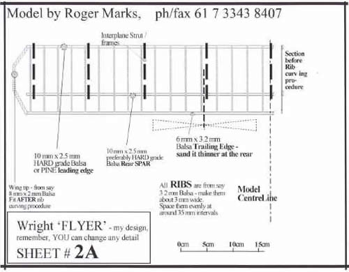
Here is Revised WING detail - it has been resized a little.
Rib Curving procedure
In Sheet 2 A showing WING detail you'll notice mention of straight appearance of wing section BEFORE Wing Curving Procedure. To simplify your construction and yet arrive at a suitable AEROFOIL wing section I have tried following.
Glue up all wing elements except wing TIPS on a flat surface. In fact, ribs are best cut STRAIGHT and LATER curved. If you first cut a length of say 3.2 mm flat Balsa about 10 cm wide to the required LENGTH of ribs, they can then be cut from this ALONG the grain with a trimming knife.
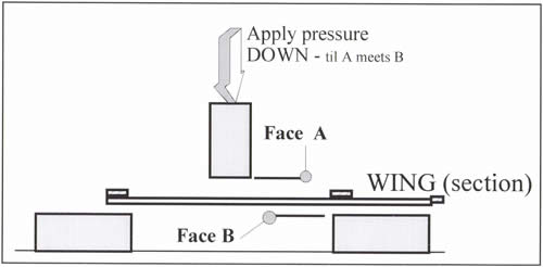
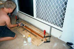
Study the photo (below) of a wing temporarily clamped in a frame easily made up from scrap timber. I'll make up a sketch to show this clamping. Essentially, Balsa will take up a curved shape when wetted with water, maybe best HOT but I found it's OK with cold water.
Now I shall add Sheet 3 showing Elevators.
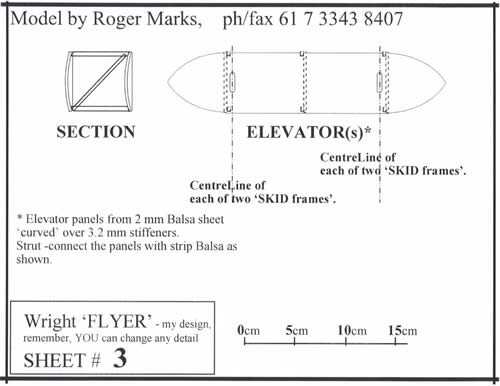
Elevator construction Notes
Curved ends are simply 'arcs of a circle'. Suggest you find a saucer (from a tea cup) and check if it 'looks about right size'. A suitably sized plate or saucer can be used as a template around the edge of which your trimming knife will cut the elevator end shape(s). DON'T drag (cut) your trimming blade AGAINST the grain !
Best to cut the slots in the lower elevator BEFORE curving and glueing it to its three stiffener pieces (Balsa). Wrap a strip of 'Magic (transparent) Tape' around the panel in each of the two slot positions taking care to position the tape so it won't interfere with where you need to glue adjacent stiffeners. Drill two holes through the taped part to form the ends of a slot. Cut between these holes with trimming knife to make the slot. The slot is of course for allowing the vertical stem of the SKID frame to penetrate and allow pivoted movement of the elevators to a suitable angle of 'incidence'.
Pivot connection at top of SKID frame vertical meeting top Elevator panel will be discussed later.
In Sheet 1A you'll see Elevators shown with some 'incidence' - i.e. sloping upwards. The optimum angle will depend on flying performance. Suggest you make slots in lower elevator panel just comfortable for vertical penetration and make the 'adjustment' by way of temporary sticky tape connections of verticals where they meet top panel. When optimum position is found you can consider a more permanent glueing.
Propeller notes
Make from 2 mm sheet Balsa with a couple of extra thicknesses around 'boss' area. I made up from scrap wood, a jig based on producing a 90 deg' twist in completed prop. At one end of a length of rectangular section timber a little longer than the finished prop, I simply fashioned a pair of small timbers screwed together as a clamp, on one edge. I then made a similar clamp on the adjacent face at the other end..
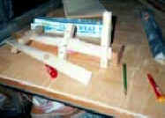
I played 'safe' and fashioned a further clamp midway along the prop length (in the 'boss' position) but you may not need that finesse.
Wet the strips of Balsa precut to width in HOT water, twist the strip(s) and then clamp them in your jig. Once securely clamped pour more hot water on them as required. This is something you should experiment with - allow to 'set' over night. Observe over a few days to see if some of the twist is lost permanently.
For simplicity you may try making two IDENTICAL props instead of going for 'contra rotating' propellers, as was the actual case with the Wright FLYER. If you opt for similar (identical) props they can be 'laid up' in the jig together. Whatever you decide here be sure ultimately, to wind the props in the correct direction.
Here is Sheet 4 showing the 'frames' I call 'Interplane Strut Frames'. (ISFs) Important notes on that part will follow, including my suggestions for JIGGING.
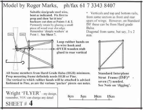
A JIG is any sort of template which facilitates the making of SEVERAL items more or less ensuring their SIMILARITY if not their IDENTICAL size etc,. You can use this ploy as follows;
Obtain a sheet of plywood or perhaps chipboard. Its size needs to be sufficient to allow the marking out by marker pen of the elements you need such as WING (2 needed) Interplane Strut frames (in all 9 are needed, 2 of which mount propellers) and what I call 'SKID frames' (See Sheet 5). Two skid frames are needed. Perhaps a large sheet might enable several team members to work on these separate parts simultaneously.
Glue will inevitably ooze out of most of these joint s when you frame is laid up so to avoid this surplus adhering to your baseboard I suggest you rub all joint areas with a cake of soap. Bullet head nails, 25 mm long by 1.25 mm diameter I find good for this next part. Three such nails tapped into the board, two on the lefthand edge (one near top and other near bottom ) of say one of the verticals of an Interplane Strut frame are sufficient to keep that element in line over its marked out representation on the board. One more nail at EACH end would FIX it in place but you may frequently get away with one such end treatment.
When you have cut all pieces and are ready to lay up a frame pause to ensure you have decided WHICH elements go on the board first. You may benefit from observing say a MIRROR image applying to the Interplane Strut frames (ISF) on LEFT (PORT) compared to those for RIGHT (STARBOARD) side. To achieve this you may at times, need simple packer pieces to support an element in places at frame member thickness proud of the baseboard Remember, simple WEIGHTS (or tools) may be useful at times to apply pressure at glued joints. Glass bead / head dressmaking pins are still needed at many joints to hold bits in place till glue sets.
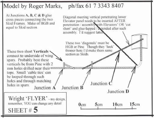
Notes on Rudder Box and its attachment
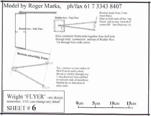
Sheet 6 shows most of what's necessary but some caution is needed concerning the fixing of the Rudder Box to its top and bottom frames.
It seems wise to make these fixings temporary until flight performance is known. However, the bottom connection needs to provide some rigidity because without same, a 'diagonal brace in the 'vertical plane' would be needed. Therefore, I suggest you drill a hole in both the base of the Rudder Box and the triangular bit of the bottom frame. Pass a small plastic electrical cable tie through and tighten. When flight performance is proven you can remove cable tie and glue the joint.
Back in Sheet 4 we had some detail concerning the 'dimple washers' which are needed to act as thrust bearings on the prop shafts.
A note now on 'fabric covering to wings'. This is traditionally furnished in tissue paper and you'll need suitable 'dope', both recommended obtained from a model supplies shop.
It's probably best to leave covering of wing surfaces until both wings are joined to all ISFs, but probably before you join Skid frames etc to the wing structure.
I'd suggest cutting sections of wing covering tissue each a little longer than the dimension between ISFs. Use glue to fix tissue to wooden members but don't strive for any real tautness - this will come later when the completely covered (top and bottom faces) wing(s) are covered. Doping then will deliver a neat taut (terrific !) job.
You should now be ready to test fly !! HOWEVER, I'd strongly recommend that testing is done when LAUNCHER device is ready. You can have the whole set-up mounted on a table and after selecting a 'thick grassy' patch out in the field TESTING can begin. Best of luck.
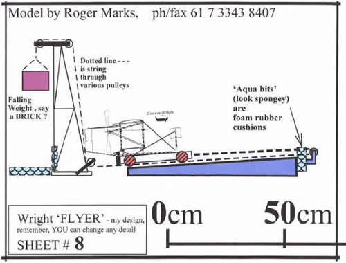
Launcher Notes
My Sheet 8 shows the basics for this. I envisage the little wheeled trolley having an upstanding lip at rear against which the rearmost cross-brace between Skid Frames can rest.(See Sheet 5 ). The model will simply separate from trolley at end of its short run, up-hill. You'll need to watch things like weight of trolley compared to BRICK etc, because IF trolley mass is too much you won't have good acceleration of trolley AND model.
Remember, your Launcher device AND model should benefit by temporary set-up on a TABLE which can conveniently be trotted out to a soft grassy part of the school ground for testing and equally quickly returned to the workshop area for adjustment.
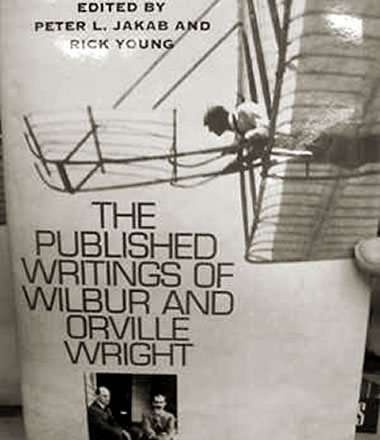
My very best wishes for a rewarding experience. If you find any photos of the real glider launcher devices of 100 years ago please tell me. ….ah..ha..!! on my recent visit to the Smithsonian Institution in Washington DC (USA) I found in the bookshop there, the following book (see cover below), and in it a PICTURE of this procedure dated 1908.
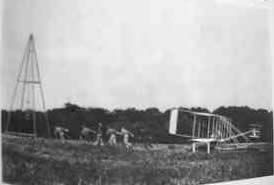
not very distinct but the caption reads … Take off in 1908. After Kitty Hawk the Wrights used a tower with a drop-weight to help launch their aircraft. Here soldiers raise the weight in preparation for a flight at Fort Myers, Virginia during the US Army Signal Corps flight trials conducted by Orville in 1908.
More Information:
Let me know HOW your model flew.